With single spur gears, a set of gears forms a gear stage. If you connect several gear pairs one after another, that is referred to as a multi-stage gearbox. For each gear stage, the path of rotation between the drive shaft and the result shaft is usually reversed. The entire multiplication element of multi-stage gearboxes is definitely calculated by multiplying the ratio of each gear stage.
The drive speed is reduced or increased by the factor of the apparatus ratio, depending on whether it is a ratio to slow or a ratio to fast. In nearly all applications ratio to slow is required, since the drive torque is multiplied by the overall multiplication aspect, unlike the drive swiftness.
A multi-stage spur gear can be realized in a technically meaningful way up to gear ratio of approximately 10:1. The reason behind this lies in the ratio of the amount of teeth. From a ratio of 10:1 the driving gearwheel is extremely small. This has a negative influence on the tooth geometry and the torque that is being transmitted. With planetary gears a multi-stage gearbox is incredibly easy to realize.
A two-stage gearbox or a three-stage gearbox can be achieved by basically increasing the space of the ring equipment and with serial arrangement of many multi stage planetary gearbox individual planet stages. A planetary gear with a ratio of 20:1 could be manufactured from the average person ratios of 5:1 and 4:1, for instance. Instead of the drive shaft the planetary carrier provides the sun gear, which drives the next planet stage. A three-stage gearbox is definitely obtained through increasing the distance of the ring equipment and adding another planet stage. A transmission ratio of 100:1 is obtained using individual ratios of 5:1, 5:1 and 4:1. Basically, all individual ratios can be combined, which results in a sizable number of ratio options for multi-stage planetary gearboxes. The transmittable torque could be increased using additional planetary gears when carrying out this. The direction of rotation of the drive shaft and the output shaft is constantly the same, provided that the ring equipment or housing is fixed.
As the amount of equipment stages increases, the efficiency of the overall gearbox is reduced. With a ratio of 100:1 the effectiveness is lower than with a ratio of 20:1. In order to counteract this scenario, the actual fact that the power loss of the drive stage is usually low must be taken into factor when using multi-stage gearboxes. That is achieved by reducing gearbox seal friction loss or having a drive stage that’s geometrically smaller, for example. This also reduces the mass inertia, which is advantageous in powerful applications. Single-stage planetary gearboxes are the most efficient.
Multi-stage gearboxes can also be realized by combining different types of teeth. With the right position gearbox a bevel equipment and a planetary gearbox are simply combined. Here as well the entire multiplication factor may be the product of the individual ratios. Depending on the type of gearing and the type of bevel equipment stage, the drive and the result can rotate in the same direction.
Advantages of multi-stage gearboxes:
Wide range of ratios
Constant concentricity with planetary gears
Compact design with high transmission ratios
Combination of different gearbox types possible
Wide variety of uses
Disadvantages of multi-stage gearboxes (compared to single-stage gearboxes):
More complex design
Lower degree of efficiency
The automated transmission system is very crucial for the high-speed vehicles, where in fact the planetary or epicyclic gearbox is a typical feature. With the upsurge in style intricacies of planetary gearbox, mathematical modelling has become complex in nature and therefore there is a dependence on modelling of multistage planetary gearbox including the shifting scheme. A random search-based synthesis of three examples of freedom (DOF) high-acceleration planetary gearbox offers been shown in this paper, which derives a competent gear shifting mechanism through designing the transmission schematic of eight swiftness gearboxes compounded with four planetary gear sets. Furthermore, with the aid of lever analogy, the transmitting power circulation and relative power effectiveness have been motivated to analyse the gearbox design. A simulation-based tests and validation have already been performed which show the proposed model is effective and produces satisfactory shift quality through better torque characteristics while shifting the gears. A fresh heuristic method to determine appropriate compounding arrangement, based on mechanism enumeration, for developing a gearbox design is proposed here.
Multi-stage planetary gears are widely used in many applications such as for example automobiles, helicopters and tunneling uninteresting machine (TBM) because of their benefits of high power density and large reduction in a little volume [1]. The vibration and noise problems of multi-stage planetary gears are at all times the focus of attention by both academics and engineers [2].
The vibration of simple, single-stage planetary gears has been studied by many researchers. In the early literatures [3-5], the vibration framework of some example planetary gears are identified using lumped-parameter models, however they didn’t give general conclusions. Lin and Parker [6-7] formally determined and proved the vibration structure of planetary gears with equal/unequal planet spacing. They analytically categorized all planetary gears modes into exactly three categories, rotational, translational, and planet modes. Parker [8] also investigated the clustering phenomenon of the three setting types. In the latest literatures, the systematic classification of settings had been carried into systems modeled with an elastic continuum ring gear [9], helical planetary gears [10], herringbone planetary gears [11], and high acceleration gears with gyroscopic results [12].
The natural frequencies and vibration settings of multi-stage planetary gears also have received attention. Kahraman [13] set up a family group of torsional dynamics versions for substance planetary gears under different kinematic configurations. Kiracofe [14] developed a dynamic model of substance planetary gears of general description including translational degrees of freedom, which enables thousands of kinematic combinations. They mathematically proved that the modal characteristics of substance planetary gears had been analogous to a simple, single-stage planetary gear system. Meanwhile, there are various researchers focusing on the nonlinear dynamic characteristics of the multi-stage planetary gears for engineering applications, such as TBM [15] and wind turbine [16].
According to the aforementioned models and vibration framework of planetary gears, many researchers worried the sensitivity of the natural frequencies and vibration settings to system parameters. They investigated the result of modal parameters such as for example tooth mesh stiffness, world bearing stiffness and support stiffness on planetary gear organic frequencies and vibration modes [17-19]. Parker et al. [20-21] mathematically analyzed the effects of design parameters on natural frequencies and vibration modes both for the single-stage and compound planetary gears. They proposed closed-type expressions for the eigensensitivities to model parameter variations according to the well-defined vibration mode properties, and founded the relation of eigensensitivities and modal energies. Lin and Parker [22] investigated the veering of planetary equipment eigenvalues. They utilized the structured vibration modes to show that eigenvalue loci of different mode types always cross and the ones of the same setting type veer as a model parameter is definitely varied.
However, most of the existing studies only referenced the technique used for single-stage planetary gears to analyze the modal features of multi-stage planetary gears, as the differences between these two types of planetary gears were ignored. Due to the multiple levels of freedom in multi-stage planetary gears, more detailed division of organic frequencies are required to analyze the impact of different system parameters. The aim of this paper is definitely to propose a novel method of analyzing the coupled settings in multi-stage planetary gears to analyze the parameter sensitivities. Purely rotational degree of freedom models are accustomed to simplify the analytical investigation of gear vibration while keeping the main dynamic behavior generated by tooth mesh forces. In this paper, sensitivity of natural frequencies and vibration settings to both equipment parameters and coupling shaft parameters of multi-stage planetary gears are studied.
1. Planetary gear sets are available in wide reduction gear ratios
2. Gear arranged can combine the same or different ratios
3. Planetary gear set comes in plastic, sintered metal, and steel, based on different application
4. Hight efficiency: 98% efficiency at single reduction, 95% at double reduction
5. Planetary gear established torque range: Low torque, middle torque, high torque
6. Easy connecting with couplings, input shafts, output shafts
The planetary gear is a special type of gear drive, where the multiple planet gears revolve around a centrally arranged sun gear. The earth gears are mounted on a world carrier and engage positively within an internally toothed band equipment. Torque and power are distributed among several planet gears. Sun gear, planet carrier and band equipment may either be generating, driven or fixed. Planetary gears are found in automotive building and shipbuilding, aswell as for stationary use in turbines and general mechanical engineering.
The GL 212 unit allows the investigation of the dynamic behaviour of a two-stage planetary gear. The trainer contains two planet gear pieces, each with three world gears. The ring gear of the first stage is usually coupled to the planet carrier of the second stage. By fixing individual gears, you’ll be able to configure a total of four different transmitting ratios. The gear is accelerated with a cable drum and a variable set of weights. The set of weights is raised with a crank. A ratchet prevents the weight from accidentally escaping. A clamping roller freewheel allows free further rotation following the weight offers been released. The weight is usually captured by a shock absorber. A transparent protective cover helps prevent accidental contact with the rotating parts.
In order to determine the effective torques, the power measurement measures the deflection of bending beams. Inductive rate sensors on all drive gears allow the speeds to be measured. The measured ideals are transmitted directly to a Computer via USB. The data acquisition software is included. The angular acceleration could be read from the diagrams. Effective mass moments of inertia are determined by the angular acceleration.
investigation of the dynamic behaviour of a 2-stage planetary gear
three world gears per stage
four different transmission ratios possible
gear is accelerated via cable drum and variable set of weights
weight raised by hand crank; ratchet prevents accidental release
clamping roller freewheel allows free further rotation following the weight has been released
shock absorber for weight
transparent protective cover
drive measurement on different gear levels via 3 bending pubs, display via dial gauges
inductive speed sensors
GUNT software program for data acquisition via USB under Windows 7, 8.1, 10
Technical data
2-stage planetary gear
module: 2mm
sun gears: 24-tooth, d-pitch circle: 48mm
planet gears: 24-tooth, d-pitch circle: 48mm
band gears: 72-tooth, d-pitch circle: 144mm
Drive
group of weights: 5…50kg
max. potential energy: 245,3Nm
Load at standstill
weight forces: 5…70N
Measuring ranges
speed: 0…2000min-1
230V, 50Hz, 1 phase
230V, 60Hz, 1 phase; 120V, 60Hz, 1 phase
UL/CSA optional
he most basic form of planetary gearing involves three sets of gears with different degrees of freedom. World gears rotate around axes that revolve around a sun gear, which spins in place. A ring equipment binds the planets on the outside and is completely fixed. The concentricity of the earth grouping with the sun and ring gears implies that the torque bears through a 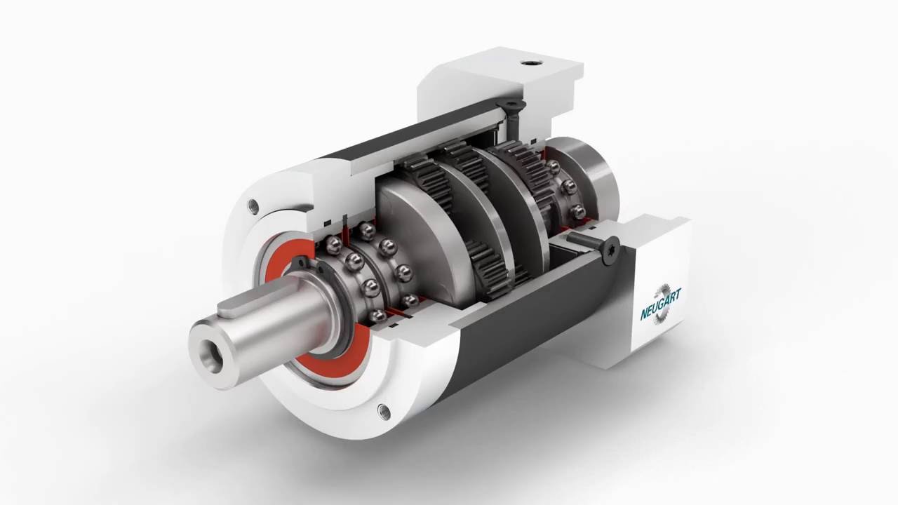 straight range. Many power trains are “comfortable” prearranged straight, and the absence of offset shafts not only decreases space, it eliminates the necessity to redirect the power or relocate other components.
In a straightforward planetary setup, input power turns sunlight gear at high acceleration. The planets, spaced around the central axis of rotation, mesh with sunlight and also the fixed ring gear, so they are forced to orbit because they roll. All the planets are installed to an individual rotating member, called a cage, arm, or carrier. As the earth carrier turns, it provides low-speed, high-torque output.
A fixed component isn’t constantly essential, though. In differential systems every member rotates. Planetary arrangements such as this accommodate a single output driven by two inputs, or an individual input driving two outputs. For example, the differential that drives the axle within an automobile can be planetary bevel gearing – the wheel speeds represent two outputs, which must differ to handle corners. Bevel gear planetary systems operate along the same basic principle as parallel-shaft systems.
Even a simple planetary gear train offers two inputs; an anchored band gear represents a continuous insight of zero angular velocity.
Designers can go deeper with this “planetary” theme. Compound (instead of simple) planetary trains have at least two world gears attached in line to the same shaft, rotating and orbiting at the same rate while meshing with different gears. Compounded planets can have got different tooth numbers, as can the gears they mesh with. Having this kind of options greatly expands the mechanical options, and allows more reduction per stage. Compound planetary trains can easily be configured therefore the planet carrier shaft drives at high velocity, while the reduction issues from the sun shaft, if the developer prefers this. One more thing about substance planetary systems: the planets can mesh with (and revolve around) both set and rotating external gears simultaneously, hence a ring gear isn’t essential.
Planet gears, because of their size, engage a lot of teeth because they circle the sun equipment – therefore they can certainly accommodate many turns of the driver for every result shaft revolution. To perform a comparable decrease between a standard pinion and gear, a sizable gear will have to mesh with a fairly small pinion.
Simple planetary gears generally provide reductions as high as 10:1. Substance planetary systems, which are far more elaborate than the simple versions, can offer reductions many times higher. There are obvious ways to further reduce (or as the case may be, increase) rate, such as for example connecting planetary phases in series. The rotational result of the 1st stage is from the input of the next, and the multiple of the average person ratios represents the ultimate reduction.
Another choice is to introduce standard gear reducers right into a planetary train. For instance, the high-velocity power might pass through an ordinary fixedaxis pinion-and-gear set before the planetary reducer. This kind of a configuration, called a hybrid, is sometimes preferred as a simplistic alternative to additional planetary levels, or to lower insight speeds that are too high for some planetary units to handle. It also provides an offset between your input and result. If a right angle is needed, bevel or hypoid gears are occasionally attached to an inline planetary program. Worm and planetary combinations are rare since the worm reducer alone delivers such high changes in speed.
multi stage planetary gearbox
Tags: