
Meanwhile, our products are manufactured according to high quality standards, and complying with the international advanced standard criteria.
Overview
Quick Details
- Applicable Industries:
-
Manufacturing Plant, farms
- Place of Origin:Zhejiang, China
- Brand Name:
-
OEM
- Product name:
-
NL1 GEAR COUPLING
- Color:
-
Black
- Surface Treatment:
-
Blackening
- Body Material:
-
45# Steel
- MOQ:
-
1 Set
- Packing:
-
Carton
- Certification:
-
ISO9001:2008
- Length:
-
37-69
The PTO shaft is the mechanical device that transfer the power from the tractor to the agricultural implement. The PTO shaft is made of two joints connected by telescopic tubes: one joint connects the outer tube of the PTO shaft with the tractor power take-off , the other joint connects the inner tube of the PTO shaft with the implement. The range of the EPG GROUP PTO shafts includes 9 sizes of different dimensions according to the power to be transferred . The sizes of the EPG GROUP PTO shafts and the power that can be transferred at 540 rpm are : SIZE 1 up to 16HP SIZE 2 up to 21HP SIZE 3 up to 30 HP SIZE 4 up to 35HP SIZE 5 up to 47HP SIZE 6 up to 60HP SIZE 7 up to 70HP SIZE 8 up to 90HP SIZE10 up to 110HP
- Bore type:
-
Finished Bore
- Model:
-
NL1
Supply Ability
- Supply Ability:
- 9999 Bag/Bags per Day
Packaging & Delivery
- Port
- shanghai
-
Lead Time
: -
Quantity(Bags) 1 – 222 >222 Est. Time(days) 12 To be negotiated
Online Customization
Worm Gear reducers are utilized in power transmission applications requiring high ratio speed reduction in a limited space. The gears are used on right angle, non-intersecting shafts. When properly aligned, worms and worm gears are the quietest and smoothest form of gearing. One drawback of worm gearing is as the ratio of this gearing increase, the efficiency of the gearing decreases. A worm gear reducer is a right angle speed reducer that allows the maximum speed reduction in the smallest package.

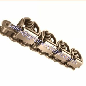
A gear coupling is a mechanical device for transmitting torque between two shafts that are not collinear. It consists of a flexible joint fixed to each shaft. The two joints are connected by a third shaft, called the spindle.
Each joint consists of a 1:1 gear ratio internal/external gear pair. The tooth flanks and outer diameter of the external gear are crowned to allow for angular displacement between the two gears. Mechanically, the gears are equivalent to rotating splines with modified profiles. They are called gears because of the relatively large size of the teeth.
Gear couplings and universal joints are used in similar applications. Gear couplings have higher torque densities than universal joints designed to fit a given space while universal joints induce lower vibrations. The limit on torque density in universal joints is due to the limited cross sections of the cross and yoke. The gear teeth in a gear coupling have high backlash to allow for angular misalignment. The excess backlash can contribute to vibration.
Gear couplings are generally limited to angular misalignments, i.e., the angle of the spindle relative to the axes of the connected shafts, of 4-5°. Universal joints are capable of higher misalignments.
Advantages of EPT gear coupling
1. Lowest price based on large scale production.
2. High and stable quality level.
3. Widely used in various mechanical and hydraulic fields.
4. Compensation for axial, radial and angular misalignment.
5. Convenient axial plugging assembly.
6. No brittlement at low temperature.
7. Good slippery and frictional properties.
8. Resistance to chemical corrosion.
9. Rich experience working with big companies in this field.
Design advantages
The Flexible Coupling method of connecting rotating shafts is a vital and necessary technique. Large massive shafting, loosely mounted in sleeve bearings and merely joined together by rigidly bolted flanges, cannot provide efficient mechanical power transmission. Especially today, as machine designers and builders demand higher speeds, higher torques, and higher misalignment capacities, the need for “flexibly connecting” this equipment becomes apparent.
A flexible coupling is necessary since it is practically Adhering to “Survival by Quality, Development by Technology & Credit”, The company will constantly improve product performance to meet the increasing customer requirements in the rigorous style of work. impossible to achieve and maintain perfect alignment of coupled rotating shafts. During initial assembly and installation, precise alignment of the shaft axes is not only difficult to achieve but in many cases it is economically unfeasible. During operation, alignment is even more difficult to maintain. Shaft misalignment – caused by uneven bearing wear, flexure of structural members, settling of foundations, thermal expansion, shaft deflection and other factors – is an operating certainty. Because these factors are extremely difficult to control, a flexible coupling serves as an ideal answer to compensate or minimize the effects of unavoidable misalignment and end movement of coupled shafts.
A flexible coupling must provide three basic functions:
1. Physically couple together two rotating shafts for efficient transmission of mechanical power, transferring the torque of one shaft to the other, directly and with constant velocity.
2. Compensate for all types of misalignment between rotating, connected shafts without inducing abnormal stresses and loads on connected equipment, and without tangible loss of power.
3. Compensate for end or axial movement of the coupled shafts, preventing either shaft from exerting excessive thrust on the other and allowing each to rotate in its normal position.

The Flexible Coupling method of connecting rotating shafts is a vital and necessary technique. Large massive shafting, loosely mounted in sleeve bearings and merely joined together by rigidly bolted flanges, cannot provide efficient mechanical power transmission. Especially today, as machine designers and builders demand higher speeds, higher torques, and higher misalignment capacities, the need for “flexibly connecting” this equipment becomes apparent.
A flexible coupling is necessary since it is practically impossible to achieve and maintain perfect alignment of coupled rotating shafts. During initial assembly and installation, precise alignment of the shaft axes is not only difficult to achieve but in many cases it is economically unfeasible. During operation, alignment is even more difficult to maintain. Shaft misalignment – caused by uneven bearing wear, flexure of structural members, settling of foundations, thermal expansion, shaft deflection and other factors – is an operating certainty. Because these factors are extremely difficult to control, a flexible coupling serves as an ideal answer to compensate or minimize the effects of unavoidable misalignment and end movement of coupled shafts.
A flexible coupling must provide three basic functions:
1. Physically couple together two rotating shafts for efficient transmission of mechanical power, transferring the torque of one shaft to the other, directly and with constant velocity.
2. Compensate for all types of misalignment between rotating, connected shafts without inducing abnormal stresses and loads on connected equipment, and without tangible loss of power.
3. Compensate for end or axial movement of the coupled shafts, preventing either shaft from exerting excessive thrust on the other and allowing each to rotate in its normal position.

Product description

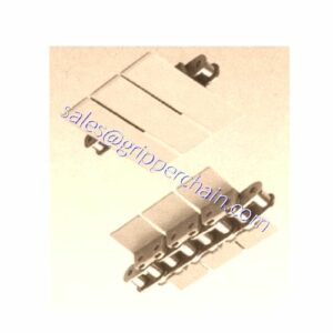
Nylon gear flexible coupling is the latest product,it has been using by abroad,and it is designed by mechanical committee of Jinan Casting forging machinery institute.
Features of NL gear coupling:
1.Absorb parallel,angular and axial misalignments
2.Simple assembly and disassembly
3.Easy maintenance and low noise
4.High tansmission efficiency
5.Long service life
|
Type |
Nominal torqueTn (N.M) |
Max speedn (r/min) |
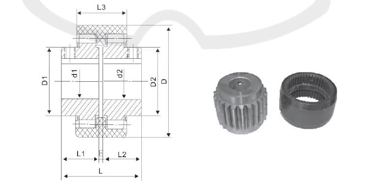
Fundamental dimensions (mm) |
Max misalignment |
Moment of inertia(KgC m 2 ) |
Mass(Kg ) |
||||||||
|
Bore diameter |
Bore length |
L |
D |
D1 D2 |
E |
L3 |
Axial (mm) |
Parallel (mm) |
Angular α° |
|||||
|
NL1 |
40 |
6000 |
6 8 10 |
16 20 25 32 |
37 45 55 69 |
40 |
26 |
4 |
34 |
2 |
±0.3 |
1° |
0.25 |
0.85 |
|
12 14 |
||||||||||||||
|
NL2 |
100 |
6000 |
10 12 14 22 |
25 32 42 52 |
57 71 91 111 |
42 |
36 |
4 |
40 |
2 |
±0.4 |
1° |
0.92 |
1.7 |
|
16 18 20 24 |
||||||||||||||
|
NL3 |
160 |
6000 |
20 22 24 |
52 62 |
113 133 |
66 |
44 |
4 |
46 |
2 |
±0.4 |
1° |
3.10 |
2.6 |
|
25 28 |
||||||||||||||
|
NL4 |
250 |
6000 |
28 30 32 |
62 82 |
129 169 |
83 |
58 |
4 |
48 |
2 |
±0.4 |
1° |
8.69 |
3.6 |
|
35 38 |
||||||||||||||
|
NL5 |
315 |
5000 |
32 35 38 |
82 112 |
169 229 |
93 |
68 |
4 |
50 |
3 |
±0.4 |
2° |
14.28 |
5.5 |
|
40 42 |
||||||||||||||
|
NL6 |
400 |
5000 |
40 42 45 |
82 112 |
230 |
100 |
68 |
4 |
52 |
3 |
±0.4 |
2° |
18.34 |
6.8 |
|
48 |
||||||||||||||
|
NL7 |
630 |
3600 |
45 48 50 |
82 112 |
229 |
115 |
80 |
4 |
60 |
3 |
±0.6 |
2° |
56.5 |
9.8 |
|
55 |
||||||||||||||
|
NL8 |
1250 |
3600 |
48 50 55 |
112 142 |
229 289 |
140 |
96 |
4 |
72 |
3 |
±0.6 |
2° |
98.55 |
26.5 |
|
60 63 65 |
||||||||||||||
|
NL9 |
2000 |
2000 |
60 63 65 |
142 172 |
295 351 |
175 |
124 |
6 |
93 |
4 |
±0.7 |
2° |
370.5 |
37.6 |
|
70 71 75 80 |
||||||||||||||
|
NL10 |
3150 |
1800 |
70 71 75 80 |
142 172 212 |
292 352 432 |
220 |
157 |
8 |
110 |
4 |
±0.7 |
2° |
1156.8 |
55 |
Company Information

Packaging & Shipping